Imaging Techniques for Detection and Management of Endoleaks after Endovascular Aortic Aneurysm Repair1
- S. William Stavropoulos, MD and
- Sridhar R. Charagundla, MD, PhD
- 1From the Department of Radiology, Division of Interventional Radiology, Hospital of the University of Pennsylvania, 3400 Spruce St, Philadelphia, PA 19104. Received October 7, 2005; revision requested November 14; revision received December 19; accepted January 16, 2006; final version accepted May 1; final review and update by S.W.S. January 11, 2007.
- Address correspondence to
S.W.S. (e-mail: stav@uphs.upenn.edu).
Abstract
Endovascular aortic aneurysm repair (EVAR) is evolving into a viable alternative to open surgical repair for many patients with abdominal and thoracic aortic aneurysms. Endoleak development is a complication of EVAR and represents one of the limitations of this procedure. Endoleaks represent blood flow outside the stent-graft lumen but within the aneurysm sac. Lifelong imaging surveillance of patients after EVAR is critical to detect endoleaks for the patient's benefit and to determine the long-term performance of the stent-graft. Although computed tomographic angiography is the most commonly used examination for imaging surveillance, magnetic resonance angiography, ultrasonography, and digital subtraction angiography all have a role in endoleak detection and management. This review will focus on imaging techniques used for endoleak detection and the role imaging surveillance plays in the overall care of the post-EVAR patient.
© RSNA, 2007
Endovascular aortic aneurysm repair (EVAR) was introduced by Parodi et al (1) in 1991 and has since been used widely as an alternative to open surgical repair for patients with abdominal and thoracic aortic aneurysms (2). As with open surgical repair, the goal of EVAR is to prevent aneurysm enlargement and rupture. The procedure involves placing a covered stent (stent-graft) in the aorta to serve as a blood flow conduit through the aneurysm sac. The stent-graft is anchored to the proximal and distal ends of the nonaneurysmal portions of the artery. The stent-graft prevents continued aneurysm growth and rupture by excluding the aneurysm and shielding the aneurysm wall from systemic blood pressure.
There are, however, several differences between open repair and endovascular aneurysm repair (2). Unlike open repair, EVAR requires lifelong imaging surveillance that is critical to evaluate the long-term success of the procedure and to detect possible complications for the patient's benefit. The most important complication to detect is aneurysm expansion and rupture that can occur even after successful EVAR (3–12). Another complication of EVAR is endoleak formation, which occurs in approximately one-fourth of patients. Endoleak is defined as a blood flow external to the stent-graft and inside the aneurysm sac (13–15). The aneurysm sac communicates with the systemic circulation through a variety of mechanisms, but the most common is reversal of flow through aortic branch vessels which then empty into the aneurysm sac (16). Endoleaks can be difficult to diagnose and treat and their management remains a source of controversy (17–23). This review will examine the techniques and challenges of imaging surveillance in post-EVAR patients and will briefly discuss options for endoleak management.
ENDOLEAK CLASSIFICATION
A classification system has evolved in which endoleaks are organized into five categories (Table 1) based on the source of blood flow (18,24–26). When describing endoleaks, it is important to remember that the source of blood flow into the endoleak defines the type of endoleak and has direct implications for patient care.
Classification Scheme for Endoleaks
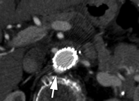
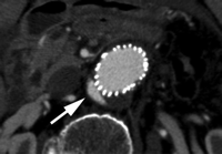
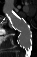
Type I endoleaks have blood flow that originates from a stent-graft attachment site. Further categorization of type I endoleaks as proximal (type Ia) and distal (type Ib) has been described (18). With either type, separation occurs between the stent-graft and the native arterial wall, creating direct communication between the aneurysm sac and the systemic arterial circulation (Fig 1). Type I endoleaks are the most common to occur after endovascular repair of thoracic aortic aneurysms (27). In addition, type I endoleaks are more common in patients with complex arterial anatomy. Short, angulated, ulcerated, trapezoidal, and thrombus-containing necks pose a challenge in constructing a seal between the stent-graft and the native aorta. Likewise, dilated, irregular, and tortuous iliac arteries present a problem for the distal attachment site in patients with abdominal aortic aneurysms. Type Ic endoleaks occur in patients with abdominal aortic aneurysms in whom aortouniiliac stent-grafts were placed in conjunction with a femoral-femoral bypass. To prevent retrograde perfusion of the aneurysm, the contralateral common iliac artery is occluded either with coils or with a specially designed occluder device. Type Ic endoleaks occur when the common iliac artery occlusion is not complete and back-filling of the aneurysm occurs. Treatment of type Ic endoleaks involves further embolization of the common iliac artery.
CT angiograms of type I endoleak in 78-year-old man. (a, b) Transverse images during arterial phase and (c) oblique sagittal maximum intensity projection show contrast material (arrow) flowing around the superior fixation of stent-graft.
CT angiograms of type I endoleak in 78-year-old man. (a, b) Transverse images during arterial phase and (c) oblique sagittal maximum intensity projection show contrast material (arrow) flowing around the superior fixation of stent-graft.
CT angiograms of type I endoleak in 78-year-old man. (a, b) Transverse images during arterial phase and (c) oblique sagittal maximum intensity projection show contrast material (arrow) flowing around the superior fixation of stent-graft.
Type II endoleaks represent retrograde blood flow through aortic branch vessels into the aneurysm sac. Type II endoleaks occur when blood travels through the branches from the portion of the aorta that has not received a stent or iliac arteries that anastomose with vessels in direct communication with the aneurysm sac. Typical sources include the inferior mesenteric and lumbar arteries (Fig 2). As is the case with type I endoleaks, a direct communication from the systemic arterial circulation to the aneurysm sac is established. Type II endoleaks are the most common type of endoleak encountered after endovascular repair of abdominal aortic aneurysms. The number of patent branch vessels and the amount of thrombus in the aneurysm sac preoperatively appear to correlate with the risk of endoleak development (28).
Type II endoleak with supply from lumbar artery in 77-year-old man. Delayed transverse postgadolinium fat-suppressed two-dimensional gradient-echo MR angiogram (repetition time msec/echo time msec, 250/1.4; 7-mm section thickness; 512 × 128 matrix, 42-cm field of view) shows contrast material accumulation in aneurysm sac (arrows).
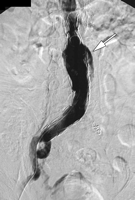
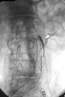
Type III endoleaks occur when there is a structural failure of the stent-graft. This includes stent-graft fractures, holes that develop in the fabric of the device, or junctional separations seen with modular devices (Fig 3). Repetitive stresses that are placed on the grafts from arterial pulsations can cause these types of leaks. In addition, as the aneurysm sac shrinks, over time additional forces are applied to the grafts that can result in graft failure. Although type III endoleaks are currently fairly unusual, they will likely become more prevalent as long-term follow-up data are accrued on the existing population of patients with stent-grafts.
(a) Frontal flush aortogram shows type III endoleak (arrow) in a patient with aortouniiliac stent-graft. (b) Arteriogram shows type III endoleak (arrow); the defect has been selected with a catheter.
(a) Frontal flush aortogram shows type III endoleak (arrow) in a patient with aortouniiliac stent-graft. (b) Arteriogram shows type III endoleak (arrow); the defect has been selected with a catheter.
Type IV endoleaks are caused by stent-graft porosity. These leaks are identified at the time of implantation as a “blush” seen on the immediate postimplantation angiogram, when patients are fully anticoagulated. These endoleaks require no specific intervention other than normalization of the coagulation profile. The diagnosis of a type IV endoleak should be one of exclusion, as other types of leaks on the immediate postimplantation angiogram can masquerade as a type IV.
Expansion of the aneurysm without the presence of an endoleak is commonly referred to as endotension or a type V endoleak. Although the exact cause of endotension is unknown, causes may include an existing type I, II, or III endoleak that is occult to traditional imaging techniques, ultrafiltration of blood across the stent-graft, or a thrombus in the sac providing an ineffective barrier to pressure transmission (18,29,30).
STENT-GRAFT COMPOSITION AND EFFECT ON IMAGING
The variety of stent-graft models has resulted in a diversity of materials used in their construction. These materials can create artifacts during imaging and may influence the choice of follow-up imaging modality, as well as the quality of these images. In addition, thickness and geometry of struts within the stent can influence the extent of artifacts generated. Stents are commonly made of nitinol, stainless steel, or elgiloy, while grafts are made of either polyester (eg, polyethylene terephthalate) or plastic (eg, polytetrafluoroethylene).
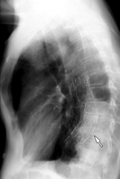
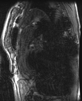
Nitinol, an alloy of nickel and titanium, causes relatively few artifacts at magnetic resonance (MR) imaging (31) and is fully compatible with MR angiography. Nitinol stents allow visualization of the stent lumen and the adjacent structures (32), though artifacts persist with some brands, which is likely related to details of stent geometry, orientation, and strut thickness (33,34). Stents composed of elgiloy, an alloy of cobalt, chromium, and nickel, may obscure the stent lumen while allowing visualization of the adjacent structures (32,33). Both nitinol and elgiloy cause only mild streak artifacts on computed tomographic (CT) scans (35). Stainless steel is a ferromagnetic material and causes an extensive susceptibility artifact during MR imaging, creating large signal voids in and around the stent (Fig 4). In addition, patients with stainless steel stent-grafts should not undergo MR imaging because of the risk of migration or deformation of the graft by the strong magnetic field. Although stainless steel can cause mild to moderate streak artifact on CT scans, CT angiography is the preferred modality for follow-up imaging in patients with stainless steel stent-grafts (Fig 5).
MR imaging artifact caused by stainless steel stent-graft. (a) Lateral radiograph shows stainless steel stent-graft (Zenith, Cook, Bloomington, Ind) in descending thoracic aorta (arrow). (b) Oblique sagittal three-dimensional gradient-echo MR image (5.2/1.7, 4-mm section thickness, 384 × 192 matrix, 38-cm field of view) shows extensive susceptibility artifact arising from stent-graft, with signal void considerably larger than stent-graft itself.
MR imaging artifact caused by stainless steel stent-graft. (a) Lateral radiograph shows stainless steel stent-graft (Zenith, Cook, Bloomington, Ind) in descending thoracic aorta (arrow). (b) Oblique sagittal three-dimensional gradient-echo MR image (5.2/1.7, 4-mm section thickness, 384 × 192 matrix, 38-cm field of view) shows extensive susceptibility artifact arising from stent-graft, with signal void considerably larger than stent-graft itself.
RECOMMENDATIONS FOR FOLLOW-UP IMAGING
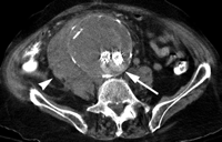
Long-term clinical data on the performance of stent-grafts are still being accumulated, but there are several reports of aneurysm rupture after stent-graft placement (6,7,36). Therefore, patients require lifelong imaging surveillance after EVAR (Fig 6).
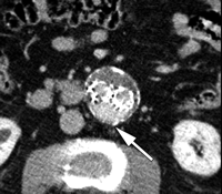
Delayed rupture of 11-cm abdominal aortic aneurysm after stent-graft placement in 81-year-old man. He was not compliant with follow-up and presented 11 months later with abdominal pain. Transverse contrast-enhanced CT scan shows extensive retroperitoneal hematoma (arrowhead), indicating aneurysm rupture and type II endoleak (arrow).
The ideal frequency for postprocedural imaging has not been determined systematically. Initial suggestions based on empiric observations of abdominal aortic aneurysms suggested follow-up contrast material-enhanced CT and radiography at 1 and 6 months after endovascular repair and then every 6 months for the remainder of the patient's life in patients with no endoleak (37). In the case of a stable or decreasing aneurysm size, conservative management of type II endoleaks is supported by a recent study (38) in which more than half of such endoleaks had spontaneously resolved. Authors of another study (39) in which 1-month, 6-month, and subsequent annual follow-up was used found that an increasing number of negative follow-up imaging studies was associated with a decreased risk of developing an endoleak; however, a delayed endoleak did occur in some patients, in one case 7 years after EVAR. Currently, at our institution patients generally undergo radiography and CT angiography 1 month, 6 months, 12 months, and then yearly after EVAR.
TECHNIQUES FOR SURVEILLANCE IMAGING
Radiography
Despite the availability of multiple advanced imaging modalities, radiography remains a useful technique for the surveillance of EVAR patients. Radiographs are still considered by some to be superior to CT scans for demonstrating the conformation of thoracic stent-grafts (40) and are important for detecting kinks in abdominal stent-grafts (41). However, improvements in multidetector CT, along with advances in image visualization tools, may require a re-evaluation of the added clinical value of radiographs. Detection of stent-graft migration is improved by consistent centering of the radiograph at the time of exposure so as to minimize geometric distortion (42). Anteroposterior and lateral radiographs can depict stent-graft migration and component separation, while oblique radiographs may improve detection of wire fractures. It is preferable to perform radiography prior to same-day CT examination so that excreted contrast material in the collecting systems does not obscure the stent-graft (43).
CT Imaging
While several imaging modalities have a place in endoleak detection, contrast-enhanced CT angiography remains the most widely used. The relative importance of CT angiography has only increased with the advent of multidetector scanners, and volumetric data sets with isotropic voxel size are routinely available with exceedingly short scanning times. The combination of speed, reproducibility, and spatial and contrast resolution have made this the preferred method of imaging follow-up, despite the associated radiation dose and the potential for nephrotoxicity.
The clinical performance of CT angiography in aneurysm imaging is well established, with documented utility in both the thoracic (44) and abdominal aorta. The high-resolution data sets allow reconstruction of thin transverse sections, multiplanar reformatted images, and three-dimensional volumes, all of which can be used to generate highly accurate aneurysm size and volume measurements. Moreover, CT angiography is able to depict endoleaks with a higher sensitivity than is conventional angiography (45,46).
Because endoleaks have variable flow rates, they can be detected at variable times after contrast material injection. For this reason, a multiphasic CT angiogram has been recommended; a typical protocol includes imaging before the administration of contrast material, imaging after the administration of contrast material in the arterial phase, and imaging in postcontrast delayed phase. Precontrast images can be helpful in differentiating calcification in the aneurysm sac from an endoleak, thereby reducing the number of indeterminate studies (47). Delayed phase imaging, in particular, is critical for it can demonstrate endoleaks that are not visualized during the arterial phase (47,48) (Fig 7). Concerns regarding radiation dose have led some investigators to consider the possibility of eliminating portions of the multiphasic surveillance CT angiography. One group (49) reported that precontrast scanning may only be necessary in the first post-EVAR examination (usually 30 days after the procedure), with all subsequent examinations acquiring only postcontrast images and using the initial precontrast scan for comparison. Since delayed postcontrast imaging depicts endoleaks with higher sensitivity than in the arterial phase, some advocate eliminating the arterial phase acquisition altogether (50). Currently, however, we believe it is important to perform the typical triphasic CT angiography (precontrast and arterial and delayed phases) in post-EVAR patients. Arterial phase images are important in planning exactly where to access the endoleak during translumbar embolization. In addition, there have been cases at our institution where endoleaks are seen only on arterial phase images and not on delayed images (51).
Transverse CT angiograms in (a) precontrast, (b) postcontrast arterial phase, and (c) postcontrast delayed phase in 78-year-old man show posteriorly located type II endoleak (arrow). Depending on their flow rates, endoleaks may be more conspicuous or larger in apparent size on delayed images because of the extra time allowed for contrast material accumulation.
Transverse CT angiograms in (a) precontrast, (b) postcontrast arterial phase, and (c) postcontrast delayed phase in 78-year-old man show posteriorly located type II endoleak (arrow). Depending on their flow rates, endoleaks may be more conspicuous or larger in apparent size on delayed images because of the extra time allowed for contrast material accumulation.
Transverse CT angiograms in (a) precontrast, (b) postcontrast arterial phase, and (c) postcontrast delayed phase in 78-year-old man show posteriorly located type II endoleak (arrow). Depending on their flow rates, endoleaks may be more conspicuous or larger in apparent size on delayed images because of the extra time allowed for contrast material accumulation.
Scanning parameters are closely dependent on the capabilities of the CT scanner. For larger numbers of detectors, the scanning can be completed more quickly by increasing the beam pitch. This reduces breath-hold time and increases the potential volume coverage, while the bolus of contrast material still resides in the arteries. With narrower detector collimation, thinner transverse sections can be reconstructed, allowing higher through-plane spatial resolution (52).
Injection of a bolus of contrast material should be modified to match the scanning parameters. As scanning duration decreases, the temporal length of the bolus can be reduced accordingly. This can be accomplished by reducing the volume of contrast material and/or increasing the rate of injection (53). Increasing the rate of injection produces higher opacification of the arteries (54,55), while reducing contrast material load can decrease the risk of renal toxicity (56).
Appropriate timing of contrast material injection is critical in performing diagnostic quality CT angiography. Several investigators have used an empiric delay time (47,57,58), which is generally acceptable for a long-lasting injection (ie, large contrast material volume or low injection rate) in patients with normal cardiac function. However, the fast injection rates, low contrast material volumes, and short scanning durations that are now possible require more precise timing of scanning, and multidetector CT angiograms often use either test-bolus injection or automated bolus tracking to achieve reliable timing of arterial phase imaging. A typical CT scanning protocol used at our institution with a 64-section scanner is given in Table 2.
Typical Protocol for Post-EVAR CT Angiography with a 64-Section Scanner
MR Imaging
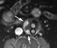
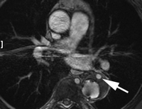
Gadolinium-enhanced MR angiography is capable of depicting endoleaks, but its performance is dependent on the composition of the stent-graft. Stents composed of nitinol are generally more suitable for MR imaging; elgiloy stents can obscure the lumen, and stainless steel stents cause extensive artifact that renders the study nondiagnostic. In several studies (59–64) involving small numbers of patients with predominantly nitinol stents, MR angiography was at least as sensitive as CT angiography, and in some cases demonstrated endoleaks that were not detected at CT angiography. In one case report (65), patients with enlarging aneurysm sacs were suspected of having endotension, but a subsequent MR angiogram demonstrated type II endoleaks that were not visible at CT angiography. In a study of thoracic aortic stent-grafts (66), MR angiography was found to be equally reliable as CT angiography in measurement of aneurysm size and stent-graft position, but did not yield the same diagnostic confidence in endoleak detection (Fig 8).
Endoleak in descending thoracic aortic aneurysm in 69-year-old man. Delayed transverse postgadolinium two-dimensional gradient-echo MR angiogram (200/2.8, 7-mm section thickness, 256 × 192 matrix, 34-cm field of view) without fat suppression shows contrast material (arrow) in anterior aspect of the aneurysm sac.
While most studies of MR angiography rely on dynamic gadolinium-enhanced three-dimensional gradient-echo and delayed two-dimensional gradient-echo sequences, new techniques such as time-resolved MR angiography may allow better characterization of the endoleak type by demonstrating the temporal evolution of contrast material in the aneurysm sac, analogous to a conventional angiogram (67,68). New blood pool MR contrast agents may improve the detection of endoleaks with slow flow rates that are occult on CT angiograms (69), although the clinical importance of these endoleaks is unknown.
US Imaging
Ultrasonography (US) is frequently used as a screening tool for abdominal aortic aneurysm detection, and some investigators have found US to be useful in post-EVAR surveillance. US is convenient, portable, safe, and inexpensive, but it is also operator dependent, with scan quality and scanning protocols varying greatly from one institution to another (70). Advances in US technology, including the use of contrast agents and tissue harmonic imaging, promise to improve its diagnostic power. In addition, standardization of scanning techniques may reduce some of the variability in the study quality. Drawbacks of US include poorer study quality in obese patients.
Aneurysm size measurements obtained with US correlate well with those obtained with CT (71–73); in one study, they were more accurate than those from transverse CT and in better agreement with those from reformatted CT (74). However, the size measurements themselves may disagree, with aneurysm measurements taken with US typically slightly smaller than the measurements taken with CT (72,73). Some investigators have found that changes in aneurysm measurement may be misrepresented at US (72,75). The demand for precise, reproducible aneurysm size measurements has led to the persistence of CT angiography in the follow-up imaging regimen.
US is also capable of depicting endoleaks. The reported sensitivities of Doppler US compared with CT vary greatly, ranging from 25% to 100% (70–73,75–78). This large range can at least partially be attributed to the differences in technique, technologist experience, and diagnostic criteria. A recent large study (79) involving 367 paired CT and US examinations after EVAR reported the sensitivity of US to be 68%. A recent meta-analysis (80) studying US detection of endoleaks reported a similar sensitivity of 69%. For endoleaks that it depicts, US can perform a level of characterization that is not available with other imaging modalities through the use of spectral Doppler analysis. Type II endoleaks with bidirectional flow (78) and low intrasac flow (81) velocities have been associated with spontaneous closure. The use of microbubble contrast agents improves the capability of US to detect endoleaks, as shown in several series (82–85) and in a recent meta-analysis (86). These agents consist of gas bubbles that are intensely echogenic and have an excellent safety profile. Early studies revealed low sensitivity (83), but later studies (84,85,87) with more recently developed agents and tissue harmonic imaging have demonstrated better results, with contrast-enhanced US occasionally depicting endoleaks that could not be seen with CT angiography or conventional Doppler US. This suggests that contrast-enhanced US could have a role as a problem-solving tool in situations of suspected endotension (85).
Nuclear Medicine
Although currently not frequently used in clinical practice, nuclear medicine scans have been used to detect endoleaks (88). Authors of a recent prospective study (88) compared the results of technetium 99m (99mTc) sulfur colloid scans and 99mTc-tagged red blood cell scans with those of CT angiography for the detection of endoleaks in 13 patients. In seven of nine (78%) patients with endoleaks on CT angiograms, the endoleaks were seen on both 99mTc sulfur colloid scans and on 99mTc-tagged red blood cell scans. However, two of the nine (22%) endoleaks seen on CT angiograms were not seen on either of the nuclear medicine scans. Four patients had no endoleak on CT angiograms and also showed no endoleak on both nuclear medicine scans. Nuclear medicine scans were less sensitive than CT angiograms for endoleak detection in this small study, but these techniques may be further refined to improve sensitivity (88).
IMPORTANT ASPECTS OF SURVEILLANCE IMAGE INTERPRETATION
The important components of imaging surveillance after EVAR include (a) measurement of aneurysm size and identification of substantial changes in aneurysm dimensions; (b) detection and, if possible, characterization of an endoleak; and (c) detection of mechanical changes in the stent-graft, including migration, kinking, and fracture. In addition, the development of Stanford types A and B dissections has been reported after stent-graft repair of the thoracic aorta (89–92), and postprocedural imaging is obviously critical in these cases. Graft limb occlusion is another potential complication (93).
Aneurysm Measurement
A critical component of aneurysm imaging is determination of the aneurysm size. Because aneurysms are often in tortuous portions of the aorta and can be irregular in shape and size, this measurement is not trivial and is subject to considerable error. Prior to the advent of endovascular repair, such errors were reasonably insignificant since surgical decisions did not require measurements with millimeter accuracy. Now, management of endoleaks is in large part determined by relatively small changes in the aneurysm size; aneurysm enlargement may prompt intervention, while aneurysm shrinkage is reassuring. Therefore, issues of reproducibility and accuracy of aneurysm measurement have come to the forefront.
Because of its high spatial resolution, CT angiography is theoretically capable of accurate aneurysm measurement, and consistent patient positioning and scanning technique contribute to excellent reproducibility. However, a measurement technique introduces a degree of imprecision and interobserver variability. Measurements derived from transverse CT images may not be representative of true aneurysm dimensions because of vessel tortuosity (74,94,95). More accurate measurements of aneurysm size can be obtained in a plane perpendicular to the center line of the vessel (95). This plane can be defined by means of multiplanar reformatted imaging, or it can be obtained from semiautomated software that determines the vessel center line.
When one compares two studies to detect a change in the aneurysm size, conventional anteroposterior and transverse dimensions obtained from transverse images may yield inaccurate measurements but actually have a lower interobserver variability than measurements from multiplanar reformatted images (95). Furthermore, single measurements of the aneurysm diameter may not adequately characterize the behavior of the aneurysm sac as a whole; discordance between aneurysm volume changes and aneurysm diameter changes have been reported (96,97), including cases of stable aneurysm diameter with increased aneurysm volume (96). For this reason, aneurysm volume measurement has been advocated as a follow-up parameter due to its low intra- and interobserver variability (95,98). Some investigators (97) have suggested that volume measurements allow an improved prediction of clinical response, while others (17) have found no advantage over standard diameter measurements. Author of a recent study (99) found that volume measurements depict aneurysm enlargement 18 months earlier than do diameter measurements. From a practical standpoint, volume measurements are likely no worse, and possibly better, than diameter measurements, but require added time and expertise for postprocessing. In addition, diameter measurements perpendicular to the aortic center line are more faithful representations of aneurysm size than those obtained from transverse images. However, if these are obtained by using multiplanar reformatted images, comparison with a previous study is most valid if the previous study is reformatted in a similar fashion.
Detection and Characterization of Endoleaks
The characteristic imaging finding associated with endoleaks is the demonstration of contrast material in the excluded aneurysm sac. In the case of Doppler US, an endoleak may manifest as a Doppler signal within the aneurysm sac. Primary endoleaks, by convention, are those that appear within 30 days of stent-graft placement, while secondary, or delayed, endoleaks are those that appear after 30 days, following at least one negative imaging finding.
Determination of the type of endoleak guides patient care. Endoleaks have variable origins, flow rates, sizes, and locations, and digital subtraction angiography (DSA) remains the standard for endoleak classification because of its high spatial and temporal resolution and its ability to depict flow direction (100). The capability of other imaging modalities to classify endoleaks has generally been ascertained in comparison with DSA.
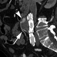
Endoleak classification with CT angiography has not been validated in large studies, but suggestive imaging findings have been described. Endoleaks located in the periphery of the aneurysm sac without contact with the stent may represent type II endoleaks. Such endoleaks with an anterior location may be supplied by the inferior mesenteric artery (Fig 9), while those that are posterolateral may be supplied by lumbar arteries. Endoleaks that are in communication with the proximal or distal attachment sites on CT angiograms may represent type I endoleaks. Endoleaks located around the graft while sparing the sac periphery may represent type III endoleaks (101), and it is important to inspect stent-graft integrity in these cases. Thin-section CT angiography can resolve vessels in communication with the endoleak cavity, but it is difficult to determine if these vessels are responsible for inflow or outflow (100). Identification of a tubular configuration in the portion of an endoleak abutting the aortic wall (peripheral tubular component) can be helpful in identifying type II endoleaks (102).
CT angiography of endoleak. Transverse (a) postcontrast arterial and (b) delayed phase images in 72-year-old man after EVAR show contrast material accumulation (arrow) in peripheral anterior aspect of aneurysm sac without communication with stent-graft. (c) Sagittal maximum intensity projection shows type II endoleak with inferior mesenteric artery (arrow) in direct communication with the area of contrast material accumulation (arrowhead).
CT angiography of endoleak. Transverse (a) postcontrast arterial and (b) delayed phase images in 72-year-old man after EVAR show contrast material accumulation (arrow) in peripheral anterior aspect of aneurysm sac without communication with stent-graft. (c) Sagittal maximum intensity projection shows type II endoleak with inferior mesenteric artery (arrow) in direct communication with the area of contrast material accumulation (arrowhead).
CT angiography of endoleak. Transverse (a) postcontrast arterial and (b) delayed phase images in 72-year-old man after EVAR show contrast material accumulation (arrow) in peripheral anterior aspect of aneurysm sac without communication with stent-graft. (c) Sagittal maximum intensity projection shows type II endoleak with inferior mesenteric artery (arrow) in direct communication with the area of contrast material accumulation (arrowhead).
Endoleak classification with Doppler US tends to be in good agreement with CT (72), and in some cases US enables correction of erroneous endoleak classification at CT (103). In a small series (104), contrast-enhanced US enabled correction of endoleak classification errors made at CT, sometimes substantially altering patient care. Development of other innovative techniques for endoleak classification is underway. Time-resolved MR angiography enabled correct classification of multiple type I endoleaks that were initially labeled type II at CT angiography (67). Dynamic CT angiography, involving repeated scanning of the same area during the inflow of contrast material, enabled categorization of endoleaks that conventional CT angiography could not (105).
Further characterization of type II endoleaks may help determine appropriate clinical management. Type II endoleaks with a large size at CT angiography, particularly endoleaks larger than 15 mm, have been associated with subsequent aneurysm expansion (106). Doppler waveforms and flow velocities obtained with US may help predict spontaneous endoleak resolution (78,81). Wash-in and washout rates of US contrast agents might be predictive of aneurysm enlargement (107). Continued evaluation of these techniques is necessary to establish their role in endoleak detection and management.
Migration, Kinking, and Fracture
The combination of chronic exposure to hemodynamic forces and changes in aneurysm dimensions can lead to stent-graft migration. The aneurysm neck can progressively enlarge after endovascular repair, and this can lead to failure of proximal fixation and migration (108–110). Alternatively, migration can be associated with inadequate overlap of the aneurysm neck with the device at the time of deployment (111,112). Stent-graft migration is associated with an endoleak, especially type I (112). Most investigators consider stent-graft migration of 5 mm or more to be substantial, and stent-graft position with respect to some consistent anatomic landmark should be noted during surveillance imaging. With CT angiography, useful landmarks of stent-graft position include nearby aortic branches, for example, the left subclavian artery, the superior mesenteric artery, or the renal arteries.
Decreased aneurysm diameter after EVAR is associated with decreased aneurysm length, which can lead to stent-graft kinking (89,113,114). Kinking is in turn associated with stent-graft migration, stent-graft thrombosis, and endoleak (115). An association between kinking and migration is also seen in the thoracic aorta, where higher flow rates and greater tortuosity may compound the problem (116). These conformational changes are important findings that are usually seen well with radiography.
Stent-grafts can fail mechanically in a variety of ways. The metal framework of the stent may fracture due to either fatigue or corrosion. The sutures holding the metal framework together can break. The graft fabric may tear. These changes can cause endoleaks, but it has also been suggested that turbulent flow in the aneurysm sac caused by a preexisting endoleak could lead to early device fatigue (117). Typically, surveillance radiographs are inspected for stent-graft fracture, although the capability of CT to detect stent-graft fracture has been reported (118).
ENDOLEAK ANGIOGRAPHY
Although CT angiography is excellent at endoleak detection, it is not as specific as DSA for endoleak classification (100). This is because CT angiography has a limited ability to determine blood flow direction, which is critical for endoleak classification. Nearly all endoleaks will cause contrast material to appear in the inferior mesenteric or lumbar arteries at CT angiography. This contrast material could represent inflow to a type II endoleak or outflow from a type I or type III endoleak. Contrast material in the inferior mesenteric or lumbar arteries at CT angiography is therefore of little value in classifying endoleaks. A recent study revealed that CT angiography did not correctly classify endoleaks in 14% of cases when compared with DSA. Reclassifying the endoleak with DSA resulted in a change in treatment for 11% of patients (100).
Endoleaks detected at our institution with CT angiography or MR angiography are usually classified with DSA before endoleak repair. The endoleak angiograms are obtained in a standardized fashion. Anteroposterior and lateral flush aortograms are obtained at the proximal attachment site with a flush catheter to evaluate for type I endoleaks. The catheter is then repositioned into the stent-graft just above the flow divider for another aortogram. Care is taken not to reflux contrast material up to the proximal attachment site. The purpose of this aortogram is to evaluate for type III endoleaks or distal type I endoleaks. The flush catheter is then exchanged for a selective catheter and selective arteriography of the superior mesenteric artery and the ipsilateral internal iliac artery is then performed. These arteriograms are obtained to evaluate for type II endoleaks. The catheter is then repositioned, with the tip over the flow divider to inject the contralateral limb. This is performed to primarily look for a type II endoleak supplied by the contralateral internal iliac artery and to look for a distal type I endoleak on the contralateral side. All DSA examinations are extended into the venous phase to allow for detection of delayed type II endoleaks. Decisions regarding therapy can be made once the endoleak is classified on the basis of DSA findings.
ENDOLEAK TREATMENT
The method of treating endoleaks is determined according to the cause of the endoleak, as demonstrated at angiography. Type I (attachment site) endoleaks are repaired immediately after diagnosis because this represents a direct communication between the aneurysm sac and the arterial blood under systemic pressures. These leaks are usually corrected by securing the attachment sites with angioplasty balloons, stents, or stent-graft extensions. Embolization of type I endoleaks has also been described (119,120).
The treatment of type II (collateral vessel) endoleaks is a source of continuing discussion and debate (16). Some authors (20,121,122) believe that type II endoleaks should be followed up indefinitely as long as the aneurysm does not increase in size. Indeed, up to 40% of type II endoleaks will spontaneously thrombose. Others believe that type II endoleaks should be repaired because these collateral vessels can transmit arterial pressure to the aneurysm sac, which places the patient at risk for aneurysm rupture (14,123–125).
Once it has been determined that a type II endoleak should be treated, it can be repaired by using a transarterial approach or a direct translumbar endoleak puncture. With the transarterial technique, a catheter is placed in the vessel of origin, usually the superior mesenteric artery or internal iliac artery. Microcatheters are then manipulated through the collateral vessels into the vessel that communicates with the aneurysm sac, usually the inferior mesenteric artery or a lumbar artery (126). Metallic coils are then used to embolize the vessel near its communication with the aneurysm sac to block the retrograde flow of blood. This procedure can be difficult and time consuming, and anatomic limitations render it impossible in some patients (127). In addition, the long-term success of this approach compared with the translumbar approach has recently come into question. Baum et al (128) showed that 80% of type II endoleaks treated in a transarterial fashion recurred compared with only an 8% of endoleaks treated in a translumbar fashion. This is because endoleaks are complex vascular structures with multiple feeding and draining vessels, similar to a vascular malformation. When transarterial approach is used, only one supply of the endoleak is embolized. Inflow can shift to a lumbar branch and recanalize the endoleak. A modification of the transarterial method involves manipulation of a microcatheter through the superior mesenteric artery and inferior mesenteric artery and into the endoleak cavity itself. The entire endoleak cavity and the feeding vessel can then be embolized, which may provide a more durable result.
Type II endoleak embolization can also be accomplished with a percutaneous translumbar approach (129–131). Endoleaks identified at previous CT angiography are referenced to bony landmarks and the stent-graft itself. The patient is placed in the prone position, and fluoroscopy is used to guide a 19-gauge 20-cm needle with a 5-F catheter (Boston Scientific, Natick, Mass) into the endoleak by using either a left or right flank approach. The proper positioning of the catheter within the endoleak is usually signaled by a free and pulsatile return of blood and opacification of lumbar arteries or the inferior mesenteric artery on manual injection of 5–10 mL of contrast material. The catheter must be placed in the patent portion of the endoleak and not in the thrombosed portion of the aneurysm. Once position in the endoleak is confirmed, the translumbar catheter can be used to embolize the endoleak. The most commonly used embolic agents are stainless steel or platinum coils (132). Liquid embolic agents such as n-butyl cyanoacrylate (Trufill; Cordis Neurovascular, Miami Lakes, Fla) have also been used with success (133).
Endoleaks due to a defect in or failure of the graft material (type III) provide direct communication between systemic arterial blood and the aneurysm sac and are therefore fixed immediately at diagnosis. Type III endoleaks can usually be corrected by covering the defect with a stent-graft extension (134). These leaks are believed to be the most dangerous because of rapid repressurization of the aneurysm sac.
Type IV endoleaks are uncommon with today's grafts but appear as aneurysm blush during immediate postdeployment angiography, while the patients are fully anticoagulated. These leaks are self limited, requiring no treatment and resolving spontaneously once the patient's coagulation status is normalized.
Because the treatment options for patients with endotension (type V endoleaks) are limited, it is important to confirm the diagnosis with multiple imaging studies. For example, if the aneurysm is expanding but no endoleak is seen at CT angiography, US and/or MR angiography should be performed as part of an exhaustive search for an endoleak. If an endoleak is found, it can be treated. If endotension is confirmed, these patients typically require conversion to open aneurysm repair, although nonsurgical management of endotension after EVAR has been described (30).
ENDOLEAK DETECTION AFTER ENDOLEAK EMBOLIZATION
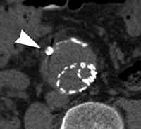
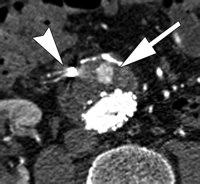
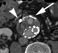
The best imaging modality for following up aneurysm size and detecting endoleaks after endoleak embolization has yet to be determined. CT angiography is the most widely used study; however, its ability to depict persistent endoleaks may be degraded by streak artifacts from embolization coils. Use of MR angiography also is difficult for endoleak detection after embolization because of artifacts from metallic coils, in particular stainless steel coils. Duplex US likely has a role in endoleak detection after embolization, but again is limited by the length of the study, operator dependence, and sometimes patient's body habitus. Findings of a recent study (135) with CT angiography after endoleak embolization have shown that despite the presence of streak artifacts, embolization coils did not prevent recurrent endoleak detection, and a high degree of interobserver agreement with regard to the measurement of aneurysm diameter and detection of a recurrent endoleak was possible (Fig 10). These preliminary data suggest that CT angiography is an adequate study for following up EVAR patients after endoleak embolization (135).
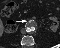
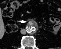
Persistent endoleak after embolization. Transverse CT angiograms (a) before contrast enhancement and during (b) arterial and (c) delayed phases show embolization coils (arrowhead) causing streak artifact and endoleak (arrow) in anterior aspect of aneurysm sac. Streak artifact from embolization coils may degrade portions of the images, but in our experience they often are of diagnostic quality.
Persistent endoleak after embolization. Transverse CT angiograms (a) before contrast enhancement and during (b) arterial and (c) delayed phases show embolization coils (arrowhead) causing streak artifact and endoleak (arrow) in anterior aspect of aneurysm sac. Streak artifact from embolization coils may degrade portions of the images, but in our experience they often are of diagnostic quality.
Persistent endoleak after embolization. Transverse CT angiograms (a) before contrast enhancement and during (b) arterial and (c) delayed phases show embolization coils (arrowhead) causing streak artifact and endoleak (arrow) in anterior aspect of aneurysm sac. Streak artifact from embolization coils may degrade portions of the images, but in our experience they often are of diagnostic quality.
CONCLUSION
Endovascular repair of aortic aneurysms is becoming an accepted alternative to open surgical repair and will likely be performed with increasing frequency. Unlike patients who are treated with open repair, patients undergoing EVAR require lifelong imaging surveillance to ensure proper stent-graft function and to detect complications. The occurrence of endoleaks after EVAR remains one of its principal complications. Endoleak detection requires rigorous follow-up with high-quality imaging. Although CT angiography is currently the most widely used imaging modality for endoleak detection, MR angiography and contrast-enhanced US continue to have an important role, which will likely expand in the future. After an endoleak has been detected, a diagnostic DSA may be necessary to classify the endoleak. Continued outcomes-based investigations will help further define when and how patients with endoleaks are optimally imaged and treated after EVAR.
ESSENTIALS
-
Lifelong imaging surveillance is necessary for a patient undergoing endovascular aortic aneurysm repair.
-
Although CT angiography is the most widely used study for endoleak detection, MR angiography can be used in patients who have been treated with MR-compatible stent-grafts or contrast-enhanced US can be used in patients with appropriate body habitus.
-
Accurate endoleak classification is critical prior to endoleak treatment; an endoleak arteriogram is often necessary to ensure proper endoleak classification.



 What's Hotlight?
